
Introduction
If you got into RC before 1985 these will probably have either slipped your mind by now, or have avoided your attention at the time. If you got into the hobby in 1987 or later, these will at best be an obscure mention in an old RC Guide Book you might have looked at.
I have a distinct memory of soldering a lead with a red 2-pin JST connector to the underside of my Grasshopper MSC in late 1985 so I could use a new Tamiya Receiver Battery Eliminator (on my “old” Acoms mk.iii radio gear) as part of a drive to upgrade it to a Hornet.
By the time I next bought a radio (a Futaba “New” Attack set), BEC had shifted to receivers, rendering this type of product obsolete.
BEC Life History
Let’s refresh our minds on what BEC means: Battery Eliminator Circuitry, any of a group of technologies aimed at doing away with the four AA size battery holder to save weight and space, reducing the voltage from the main drive battery to a safe level for the radio receiver.
This has gone through several distinct stages:
Late 1970s – Start of Tamiya RC Cars:
Resistance based Mechanical Speed Controls (MSCs) and 4xA boxes were the norm and by their nature couldn’t deliver more than the “safe” voltage for the receiver.
Ironically, the earliest cars ran on four 1.5v C cells, so it would have been perfectly safe to plumb the drive batteries voltage straight into the receiver – at least until the 6v, 5-cell Ni-Cd (Nickel Cadmium, or NiCad) packs came along.
Nb Although the nominal voltage of an Ni-Cd cell is 1.2 v, they can be 1.55v or 1.6v at the very of a delta peak fast charge – so up to 7.75v or 8v.
Early 1980s - 7.2v:
Someone thought “wouldn’t RC be more fun with 6-cell, 7.2v* batteries?” and everyone agreed. Earliest instances of BEC-like tech were used in racing, typically using a simple Zener diode.
* again, a nominal value at freshly charged 6-cell Ni-Cd might be as much as 9.3v to 9.6v.
April 1985:
The first Tamiya instance of external BEC appears, attached to the MSC of the Hot Shot. Weight and ongoing expenses are two good drivers towards getting rid of the four AA cells, but in this case it had more to do with a lack of space – there’s nowhere on a Hot Shot to put them, and making more space would have meant making it longer, wider, less realistic, or 2WD. At this point in time, Tamiya suggested cutting the connector off the battery box supplied with your radio to connect things up.
October 1985 - Tamiya BECs:
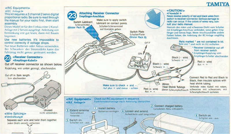
Tamiya release a line of Receiver Battery Eliminator(s) with different plugs to suit popular radio brands of the day. They use the 2-pin JST connector for the connection between MSCs and the units, which later becomes an RC industry standard.
Spring 1986: Receiver BECS:
Radio gear manufacturers started making their receivers with onboard BEC, thus making Tamiya’s units completely redundant after less than a year.
Tamiya introduces the 8.4v, 7-cell Ni-Cd battery for their flagship Bigwig with the Technigold motor (21T with variable timing). All the bodies that make the rules for racing say “nope” to 7 cells, and it never really takes off.
1990s – rise of NiMH Batteries:
Nickel Metal Hydride battery technology supplants Ni-Cd towards the end of the decade, beginning a capacity arms race that shows no signs of stopping. This has nothing to do with BEC, but I felt I had to put something here, otherwise it would look like there was no development in RC between 1986 and 2010…
2000s - Rise of ESCs:
The TEU-101BK Electronic Speed Control became the most widely used, thanks to being supplied in most Tamiya kits in non-Japanese markets for a long time). Unlike any other modern ESC it output full drive battery voltage on the JST connector - but receivers still had BEC to cope with that.
LiPo (Lithium Polymer) batteries become popular toward the end of the decade, but Tamiya pinned their tail to the lower voltage, lower capacity and “safer” Lithium-Ion donkey, mixing up “ion” with “iron” to come up with the “LiFe” acronym. Nobody else thought they were a good idea, and even Tamiya quietly dropped them after a few years.
2010s – Safe ESCs & Rise of 2.4ghz Radio
While almost every new ESC (even Tamiya, thanks to the TBLE-02S) put out a safe voltage for standard battery voltages, some new receivers (like the Acoms GR-24 for their 2.4GHz radios) stopped having any capability to reduce the incoming voltage to a safe level.
This meant if you had a new radio, but an old ESC, you needed a UBEC (Universal BEC) – and I’m sure I wasn’t the only one irritated there being no attempt at any sort of standard way of connecting to the drive battery & leaving bare wires on one end.
2020s - Lipo fails to take over
NiMH is still the battery of choice for the newcomer & casual user – and really anyone who doesn’t feel a need to extract every ounce of performance from their RC. No new developments in BEC, as yet anyway.
To summarise, the life cycle of BECs thus far has been: None -> basic external -> complex external -> on receiver -> on ESC (or external UBEC).
The Products
The Tamiya RC Guidebooks of the time group the BEC related products: six varieties of Battery Eliminators, a 2-pin connector set that could be soldered on to MSCs that weren’t already so equipped, and two options for the 3-step, 2 resistor “wiper” type MSC with a 2-pin JST lead already fitted. These reference the Hornet and Wild One, but realistically Tamiya were providing one with “regular” length motor wires, and one with “long” to accommodate a lot of prior RC cars.
The full list of products was:
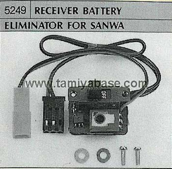
SP-249/5249/50249 Receiver Battery Eliminator For Sanwa (10 Oct 1985)
https://tamiyabase.com/parts/911-50249
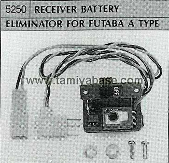
SP-250/5250/50250 Receiver Battery Eliminator For Futaba A Type (10 Oct 1985)
For the older old servo connector type with 3 exposed pins with the wiring coming off at 90 degrees.
https://tamiyabase.com/parts/912-50250
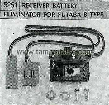
SP-251/5251/50251 Receiver Battery Eliminator For Futaba B Type (10 Oct 1985)
For the modern 3 pin format (with orientation wing)
https://tamiyabase.com/parts/913-50251
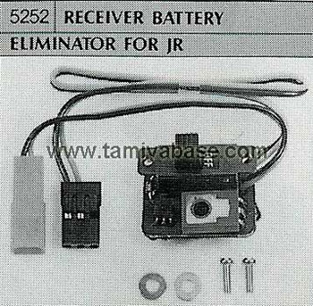
SP-252/5252/50252 Receiver Battery Eliminator For JR (10 Oct 1985)
https://tamiyabase.com/parts/914-50252
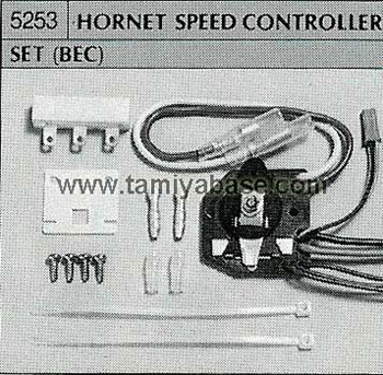
SP-5253 Hornet Speed Controller Set (BEC) (25 September 1985)
https://tamiyabase.com/parts/915-50253
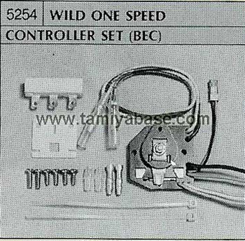
SP-5254 Wild One Speed Controller Set (BEC) (25 September 1985)
https://tamiyabase.com/parts/916-50254
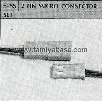
SP-5255 2 Pin Micro Connector Set (25 Oct 1985)
Now standard red 2-pin JST connectors
https://tamiyabase.com/parts/917-50255
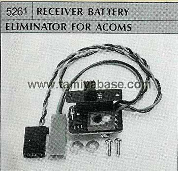
SP-261/5261/50261 Receiver Battery Eliminator For Acoms (10 Oct 1985)
This is only for the “modern” 3 pin Acoms connector – there’s no option for the “old” clip type Acoms plugs found on the “mk.i” and mk.ii Techniplus sets.
https://tamiyabase.com/parts/923-50261
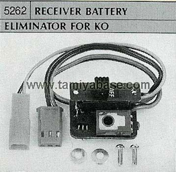
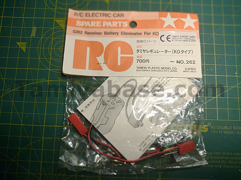
SP-262/5262/50262 Receiver Battery Eliminator For KO (10 Oct 1985)
https://tamiyabase.com/parts/924-50262
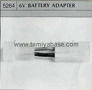
SP-5264 6v Battery Adaptor
This is a short lead allowing connection of 6v batteries to 7.2v MSCs & chargers – there’s no relation other than catalogue position and part number.
https://tamiyabase.com/parts/926-50264
The Rise of On Board BEC, and ESCs
The “new” 58041 The Fox (Japanese release date 29 Oct 1985) was used in Acoms adverts in the UK press for the “new” ARD-227 receiver with onboard BEC, however that appears to have been a prototype, with production of the “early” mk.iii sets with the ARC-227 TX giving way to the “mid” and “late” sets with the BEC equipped ARE-227TX.
By 1986, Acoms were including the ARE-227 receiver (which had onboard BEC) in their revised Techniplus Mk.iii radios, the Futaba equivalent at the time would have been the brown (“mk.i”) Futaba Attack, which also had a BEC equipped receiver - which made these Tamiya products obsolete.
However, the 2-pin JST connector had become the standard for connecting your MSC to the receiver via a switch loom, and every MSC from 1986 on came with a flying lead already attached.
While other ESC manufacturers did away with the JST lead, instead suppling a receiver safe voltage over the +ve pin on the SC “servo” lead and an on/off switch pre-attached, Tamiya went a completely different way and had full drive battery voltage on a holdover JST lead. This was fine with “old” 40mhz and 27mhz receivers with BEC, but not on the new 2.4ghz receivers that didn’t have BEC onboard, because the industry standard had moved to BEC tech being on the ESC … the problem was that most non-Japanese Tamiya RC users employed the “free” TEU-101BK ESC that came with their kit, because why wouldn’t you?
Instruction Sheets & Packaging
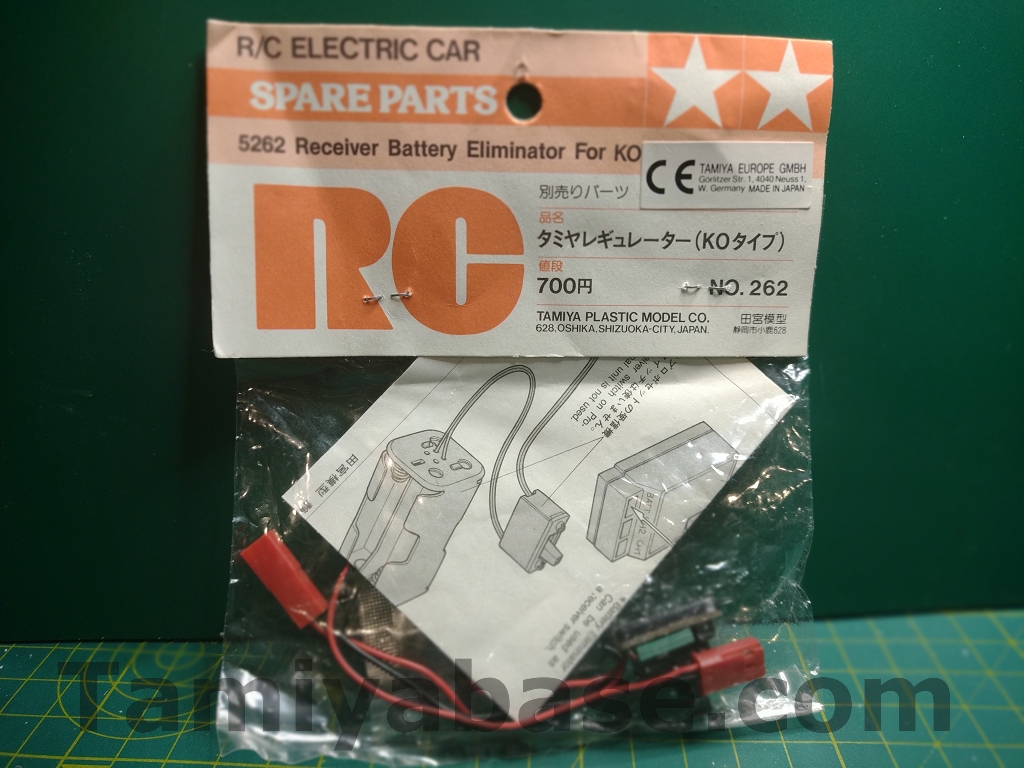
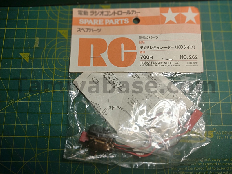
My open pack Acoms set has a date of 1985 on the instruction leaflet, as does the NIP KO set. However, the KO set also has a CE sticker applied by the German Tamiya Europe importer.
Such marking wasn’t required on electronic equipment until the 1st of January 1996 – but that’s not conclusive either way, it’s just as likely that Tamiya were still trying to get some value out of stock not sold in the previous decade. The “W” (for west) has been superfluous since 1990 too.
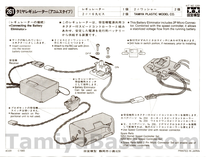
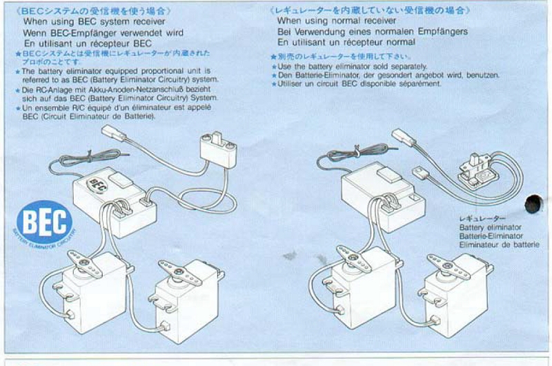
The instruction sheets, while very simple, have clearly had some time and effort expended on them. Each are broadly similar, but have an accurate representation of the particular manufacturers’ receiver, switch and plug arrangement of the time. For example, you can see the flying lead arrangement of the then-current ARC-227 RX on the 261 Acoms sheet.
Note the instruction to drill extra holes in your chassis/mount, if required – these really were a bit of a compromise.
“Early” and “Late” Versions?
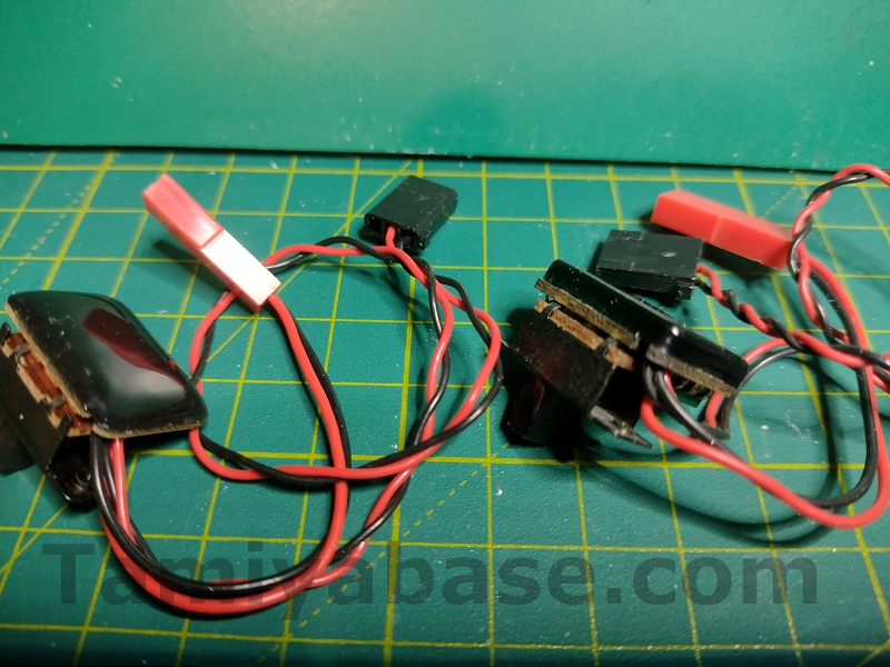
The back (or typically, top, when fitted) of the Tamiya BECS are finished in a potting compound, a black, almost completely opaque epoxy material intended to protect the soldered joints on the back of the PCB - this seems to have been applied in two distinct ways.
The first has a poured or self-levelled look to it, through which you can see (and feel, to a certain extent) the outer pins of the switch – this is how my 261 Acoms-plugged one had been finished BITD, and the loose Acoms 261 I bought recently had also been finished in the same manner.
The second variety uses the same potting compound, but in a slightly greater quantity, and, more importantly, appears to have been moulded into a form giving a more uniform look, both flatter and much squarer at the edges. This is how both my in open pack Acoms 261 and NIP KO 262 units came. All the other Tamiya sets I’ve seen for sale recently also have the same square) back.
This raises the question, are there “early” and “late” units? Or a mk.i and mk.ii, or “top down” and “bottom up” variations, depending on how you want to word it?
I would think the self-levelling method would require very accurate dosing & could have a high failure rate, so it could have been changed very early during production.
Values
While rare and somewhat interesting, values for the Tamiya Receiver Eliminators seem to be around 15 GBP, posted, with very little regard to compatible manufacturer, potting type, age, “new in pack” or otherwise.
In general, if someone wants a fully “vintage” experience of running a car with pre-BEC radio, they’ll just use a 4xAA holder – the time window where these external BECs were “correct” was very narrow at the time, and I just don’t see anyone’s nostalgia being contingent on using one of these instead.
Conclusion
Right at the beginning I asked whether external BECs were a necessary step to better (i.e. on board) circuitry. However, I’m not sure that’s even the right question. If it was a case of Tamiya and radio manufacturer’s seeing the basic, diode-based voltage droppers in RC racing & Tamiya going off to do their own thing while radios went another, you could look at it as Tamiya going all in on the wrong technology.
However, the Hot Shot really needed some way of losing the 4xAA batteries, and it’s to Tamiya credit that they developed a neat, advanced circuit to do so. Making the units available on their own only seems a mistake once you know what happened later – although it was less than a year later.
Maybe the correct question is do you need one? The Hot Shot is the only vintage Tamiya RC car that really had to have an external BEC - and one comes already connected to the MSC in the kit.
By the time we get to other 4WD cars (like the Boomerang, April 1986; the Bigwig in July 1986) and smaller scale 4WD cars (like the Porsche 959 from October 1986), most current radio sets would have had BEC on the receiver and that’s what Tamiya suggest you use, with an external BEC being only an option.
The answer is probably no, you don’t need one unless you have a Hot Shot with a broken one, or are trying to recreate a very specific setup you had back in the day.
________________________
Written by TB member Jonny Retro