Actually... according to this formula only two of these variables are influenced by efficiency. One factor on the left of the equation and one on the right... That would mean torque remains constant and only power and rpm are influenced by efficiency loss. I think there might be something I'm not seeing... Edit - or maybe not. I just read up. P = V * i is the electrical power P = T * ? is the mechanical power Between them is efficiency loss from the energy conversion. The current (i) is directly related to torque (T). This will have no drop. Power loss (heat, friction) translates into a lower maximum of revs. When brands say it was measured "at best efficiency" they act like the motor is 100% efficient. As if the first equation were equal to the second... With eddrick's motor I even suspect them to have miscalculated this into adding an extra efficiency factor to torque. Making it twice what it would actually be... But would a fabricator of electro motors really have made this mistake? That would be really something. Wonder what Louisbaby would have to say about this btw. He's got a dyno. |
|
|
Please Log in to join the conversation.
Last edit: by Edou.
|
|
I'm gonna take a flyer & say there's a lot of complex electromechanics going on in a turning motor & simple equations can't tell the story of the machine as a whole.
eg you can look at winding resistance with V=I.R, but ONLY when the rotor's stationary - as soon as it starts moving you have to start taking conductance & reverse EMFs into consideration as the rotor electromagnets (Windings) pass the fixed permanent field magnets. This new conductance & reverse EMF WILL vary depending on the position of the rotor relative to either of the field magnets too (ie the effects will be different with the rotor in line with the magnets than when it's in line with the EDGE of the magnets, approaching or leaving them). Adding to this, the varying effect of the permanent field on the rotor windings will cause heating effect, which in turn will affect the V=I.R equation, as the 'R' has effectively changed it's value due to the different temperature. This is just a glorified example, but I think if you look close enough you'll find similar scenarios with P=V.I In fact, substitute in V gives P=I.I.R & there we have it, R is complex as described above, showing P is influenced at a complex changing rate, & that's only looking at the windings! I think that settles it for me, real-time dyno results under specified conditions can be the only reliable figures, & the 'specified conditions' would have to be the same for any manufacturer's tests, to make the comparisons fair/accurate. They would also have to have various 'sets' of these conditions, so you could see at a glance whether a motor is more suited for speed, torque or run-time & indeed what level of speed/torque/runtime you were getting. ALTERNATIVELY, buy a dyno & test the motors at the shop before handing your money over!
Custom F2
...
Hilux crossmember drawing
...
F2 axle drawing
...
Quattro radio lid
...
Holiday Buggy motor bracket drawing
...
Quattro resto
...
HitnMiss engine
...
Wild Willy resto
...
Mardave Cobra resto
...
Thunder Dragon resto
...
Grasshopper resto
...
XR311 resto
...
Modded XR311
...
Carbon 25th scratch build
|
|
|
Please Log in to join the conversation. |
|
True enough that the basic approach is a simplification...
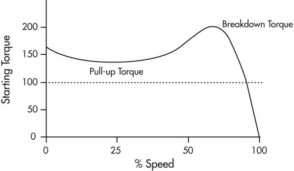
Flux and resistance will vary with different current and speed. Generally (once more) the torque-speed curve will look like this : The specs "at best efficiency" (100% speed without load) that are often given by the factory are kinda nonsense. |
|
|
Please Log in to join the conversation.
Last edit: by Edou.
|
|
Cool graph! Where did it come from? Not sure it's right though - maximum torque is at zero rpm ie all of it is present when you first apply power & before the rotor starts to turn. Least torque is when the rotor reaches its maximum rpm (Or else it would carry on accelerating), which will be set by the input voltage, available current & magnet/rotor/commutator timing (It will stop accelerating when input electrical power equals mechanical power required to rotate at that speed). However, there will be maximum rotor momentum at flat out speed, & I'm wondering if this graph is showing that added to the produced torque, or not... not sure about it now - 0 torque at 100% speed is right (As is the downward slope to it) but it's showing there's more torque at 75% speed than at startup, which definately isn't right I would've said.... maybe the graph shows the motor behaviour when hooked up to a mechanical load? OR, is it illustrating the charactaristics of whatever speed control device was hooked up to the motor during testing? - now there's a thought for you!
Custom F2
...
Hilux crossmember drawing
...
F2 axle drawing
...
Quattro radio lid
...
Holiday Buggy motor bracket drawing
...
Quattro resto
...
HitnMiss engine
...
Wild Willy resto
...
Mardave Cobra resto
...
Thunder Dragon resto
...
Grasshopper resto
...
XR311 resto
...
Modded XR311
...
Carbon 25th scratch build
|
|
|
Please Log in to join the conversation. |
|
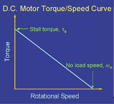
Guess it's a linear trade off after all on a DC electro motor...
This one is theoretical (no load) again : Link Guess I just didn't wanna know it 'cause I liked the other graph better. |
|
|
Please Log in to join the conversation.
Last edit: by Edou.
|
|
I cannot find any loaded curves on line but I could imagine it having somewhat of an S-curve like the earlier graph...
Another spec one could calculate - the minimum (theoretical) time capacity of your battery. Let's say you have a 3000mAh battery... Looking at the specs of your motor, this can be compared to the maximum current your motor draws. Let's say this is 12A. 3000mAh means your battery can deliver 3A for an hour long. Or 15 minutes with 12A drain... So you could run your car at least for this time because the motor will not continously draw the maximum current. The formula : Minimum run time (in minutes) = i = current draw (A) C = battery capacity (Ah) - note that C is not in mAh Our example : 60 / (12 / 3) = 15 minutes |
|
|
Please Log in to join the conversation.
Last edit: by Edou.
|
|
All starting to make sense now - previous graph is for an AC induction motor, & these aren't much to do with volts & amps, but more to do with frequency - voltage is INDUCED into the rotor by the alternating (Sine wave) current in the field coils. The induced voltage/current (Read magnetism) in the rotor makes it want to oscillate in-time with the field coil magnetism, which is changing strength & polarity in time with the supply frequency. Usually there'll be multiple field coils, one (Or more) of which will have some sort of offset (eg by capacitor in single phase motors) to get the rotor spinning in one direction. (In 3 phase, the supply phases are offset giving a natural 'order' for the field coils which are seperately attached to each of the phases, so the rotor spins). Here in the UK, supply frequency is 50Hz (60Hz in the US & other places), so the natural, most efficient rotational speed of an AC induction motor here is related to that, or multiples/factors of it, depending on how many sets of field coils (Poles) the motor has. This is why the graph is an odd shape, because the supply rail(s) are sine wave rather than constant (As in DC/battery supply) & depending on what part of the wave the rotor is trying to match at its current speed, it can 'see' varying voltage/current. Modern inverter drives (As in your link) are programmed to get the best efficiency of the motor at any speed, regardless of its frequency-matched natural speed. This probably also applies to brushless systems, as the motor mechanics are probably very similar, with field coils rather than permanent magnets, the brushless ESC being the equivalent of an AC frequency inverter, feeding the coils in order at varying frequencies which the rotor tries to follow (Never pulled one apart, but that's what I'd expect to find). This is, incidentally, why brushless ESCs & motors are so hugely expensive by comparison.
The above straight line graph for a brushed DC motor is more what I expected to see, albeit simplified (As I said before, there's a lot of other stuff going on that will affect the way a motor behaves, but the general behaviour is as the graph). Cheapest way to get some idea of what I'm on about with AC & brushless motors is to get an old PC fan & rip it to bits. Inside, you'll find a magnetic strip glued to the the rotating fan part (The rotor), & if you run a magnet around it you'll find there are multiple polarity changes around its circumference. On the stationary frame bit (The stator) you'll find 4x coils, all wired back to some electronics. The electronics feed each coil in order, with changing +/- current, (To create changing north/south magnetism) at a set frequency of change. the magnets in the rotor get attracted/repelled by the stator at that frequency, & follow the cycle around the stator. If you could change this frequency, you can change the speed, which is what the ESC or inverter is doing. Hopefully that makes some kind of sense!
Custom F2
...
Hilux crossmember drawing
...
F2 axle drawing
...
Quattro radio lid
...
Holiday Buggy motor bracket drawing
...
Quattro resto
...
HitnMiss engine
...
Wild Willy resto
...
Mardave Cobra resto
...
Thunder Dragon resto
...
Grasshopper resto
...
XR311 resto
...
Modded XR311
...
Carbon 25th scratch build
|
|
|
Please Log in to join the conversation. |
|
It's easier & makes more sense if you have the bits in front of you than trying to make sense of the black & white stuff!
Custom F2
...
Hilux crossmember drawing
...
F2 axle drawing
...
Quattro radio lid
...
Holiday Buggy motor bracket drawing
...
Quattro resto
...
HitnMiss engine
...
Wild Willy resto
...
Mardave Cobra resto
...
Thunder Dragon resto
...
Grasshopper resto
...
XR311 resto
...
Modded XR311
...
Carbon 25th scratch build
|
|
|
Please Log in to join the conversation. |