|
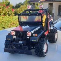
I got my third component finished. I can close the radio box now...
In terms of broken parts, for which I have no other escape than printing a new part, there is.
That makes 2/7 of it However, since It is easier to get attachement points from a given existing design, I think my next step is the gearbox right and left half. I buy kits to built and ru(i)n them
The following user(s) Liked this: Ducksnuts
|
|
Please Log in to join the conversation. |
|
Today's lesson was that it is easier to see the symmetry axis of a gearbox when you have the gears visible inside...
I started to model the left half of the gearbox... Almost used the full panel of my Confusion360 skills within a single sketch to pull just this first step... As soon as got the solid done with an extrusion and a a revolve on 180°, I did use section analysis to review the chassis and where it fits all together... There is a few things that let me think that the design is right (the gearbox symmetry axle is right at the level where the chassis halves are splitted)... I just have to offset one surface about one millimeter but it's because I offset 1 mm in the other way earlier... I believe I'm on the right path... Even if I sometimes ask myself in what I'm getting engaged I buy kits to built and ru(i)n them
|
|
Please Log in to join the conversation. |

|
Awesome 😲
The following user(s) Liked this: jord001
|
|
Please Log in to join the conversation. |
|
Measuring holes distance when the holes are at the same height is dumb easy... And when it's not at the same height, or that there is something which doesn't allow to get the caliper set right, that's were it complexe and any method may imply parallax issues...
I've ordered few 2.5mm diameter rods. They are the right size to enter in 3mm screw holes. Key assumption is that there is always a way to access holes perpendicular, as you need to put a screw in. And I've designed a tool which I plan to insert 2.5mm rods and set them perpendicular to the tool. The idea is to push the rods in the hole, and measuring the distance between the rods with the caliper. The measure will need to be offset with the the sum of the half diameter of the rods. Note that you can use different sliders with different rods diameter to adapt to the situation you want to measure... I will print this tonight. I buy kits to built and ru(i)n them
The following user(s) Liked this: stingray-63, jord001
|
|
Please Log in to join the conversation. |
|
The work on the gear box continue...
At this stage, I have three sketches for the gearbox. One for the profile, and the target is to use it as well for the right gearbox. It's not even complete as I added other things inside the sketch later on... I have another one for the motor plate profile, and one for the internals of the gearbox (basically whatever would be applied inside the gearbox after having shelled it. Then there will be 3 additional sketches for the remaining stuff (arms attachements top and bottom,and for gearbox closing fixation). Here is what I have in CAD for the left half of the gearbox - the right part is not exactly symmetric due to the motor. And the gearbox irl. I think I got the shell more or less ok. And on the whole view... The most complex things are done already, but I will need to wait the tool to be printed to check my measurements... I buy kits to built and ru(i)n them
The following user(s) Liked this: stingray-63, jord001
|
|
Please Log in to join the conversation. |
|
That's amazing.
The following user(s) Liked this: silvertriple, jord001
|
|
Please Log in to join the conversation. |
|
I've published the tool
Distances between axle holes measuring tool by silvertriple - Thingiverse I buy kits to built and ru(i)n them
The following user(s) Liked this: jord001
|
|
Please Log in to join the conversation. |
|
This morning I was not feeling well, so I dropped a message to my boss I'll get a day off and moved all my today's meeting before getting back to sleep...
And around 11 this morning, I woke up, and decided to restart the work on the left half gearbox... First work out the supports of the suspension arms.... Then t was time to be able to close the gearbox with some ears A small check is needed here... I had to review the width of the chassis shell in this area to get it correct both on the rear side and the left side, as there was no room for the screw... I made more sketches than I thought but they should be reusable for the other half of the gearbox... I have a small modification to do on two of the ears on the motor side but that will be done quite quickly, otherwise there would be no way to put a screw in there... The more I worked on this gearbox, I think I may not have started by the easiest car to model :-D I buy kits to built and ru(i)n them
The following user(s) Liked this: stingray-63, jord001
|
|
Please Log in to join the conversation. |
|
I had nothing else to do so I continued working on...
Started to work on the second half of the gearbox... A component symmetry, first. Then filling the holes, drilling new holes and extend the gearbox mount on the right side... It seems the fit is right on the chassis... Nothing really complex as the hard work was already made for the left gearbox half... Now, the main difficulty is to determine the motor position, and where I should put the extension to get it right... I confirmed first that the gearbox fixation points on the motor plate were symmetrical. Easy compared to what I've done until now.... next was to find the motor center... and position it. and then determine the diameter of the circle to use... and guess what : it seems spot on with the gear box fixation... Next was just to deal with a few extrusions, and boom, done... Not sure what I do next. I decided to delay the chassis test print when I had to modify minor details... I will probably wait I have the Bumper model to get there... I buy kits to built and ru(i)n them
|
|
Please Log in to join the conversation. |